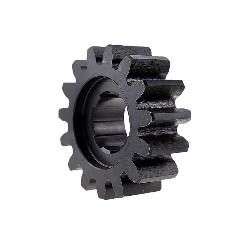
A pinion and a rack make up the steering system of a Precision rack and pinion (a linear kit). A rotating motion is transform into linear motion by the system to operate. In contrast to the recirculating ball steering found in larger trucks, larger SUVs, and other heavy-duty vehicles, most automobiles, small trucks, and SUVs are fitte with a rack and pinion system.
Rack and Pinion: Applications
Most people are familiar with Precision rack and pinion systems for steering cars and compact trucks, but they also have other uses. Rack and pinion systems improve braking control, particularly in snowy and icy circumstances, and assist trains in ascending steep grades. According to Stairlift.com, rack and pinion systems are specific parts in the majority of stairlifts. Most frequently, hydraulic or electrical power is use to drive the rack and pinion mechanism.
How Does Rack and Pinion Steering Work?
When using rack and pinion steering, a gear system converts the circular motion of the steering wheel into the linear signal required to turn the wheels. The gear set is enclose in a metal tube. The rack can be attache to an axial rod using apertures on each end of the tube. The pinion gear is attache to the steering shaft so that the gear spins and moves the frame when the steering wheel is turn. A tie rod end, which is attache to the spindle, is where the axial rods join.
Rack and pinion gear sets have two main functions:
● Reduced gears make it simpler for the steering wheel to turn the wheels.
● Conversion of the rotating motion of the steering wheel into the required linear motion for the wheels of the vehicle

Power Rack and Pinion
Observes that the rack and pinion designs on cars with power steering varied slightly. Two steel tubes run the length of a power rack, acting as pressure and return lines, as well as the left and right turning. A cylinder with a piston and two fluid openings is connected to the power rack. The piston is propelle by high-pressure fluid, which causes the rack to follow. Electric systems make use of an electric pump.
Spur gears
Spur gears are a form of cylindrical gear with straight, perpendicular teeth that are aligne with the shafts and have parallel shafts.
A spur gear’s teeth have an involute contour and mesh one at a time. Spur gears only generate radial forces (no axial forces) due to their involute design, but the way the gear teeth are meshing puts a lot of strain on them and generates a lot of noise. Spur gears can be utilize at virtually any speed. However, they are usually employed for lower-speed applications.
There are two primary types of spur gears:
● external spur gears
● internal spur gears
Precision Spur gears come in two main categories: external and internal. On the outside of the cylinder, external gears have teeth that are cut. In opposition to one another, two exterior gears mesh. In contrast, internal gears feature teeth carved out of the cylinder’s inside surface. An external gear surrounds the inner gear, and both gears revolve in the same direction. Internal gear assemblies are smaller than exterior gear assemblies due to the closer spacing of the shafts. Planetary gear drives primarily employ internal gears.

For applications that call for both speed reduction and torque multiplication, like ball mills and crushing machinery, spur gears are typically thought to be the best option. Despite their loud noise levels, consumer appliances like washing machines and blenders are examples of high-speed applications that utilize spur gears.
Straight Tooth Gears | Large Gears | custom gear design | Bevel Wheels | mechanical spur gears | Polishing Head | bevel ring gears | Cnc Gear Rack | stainless steel gears